EN
EN


Custom Electronic Connector Pins
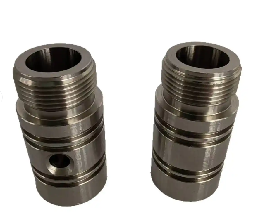
Zhengna Technology manufactures electronic connector pins to drawing using Swiss-type CNC turning and bar-fed CNC turning. Stepped diameters, shoulders, grooves, contact ends and retention features are reviewed together with the mating interface. Material, dimensional acceptance, plating zones and inspection records are agreed before quotation.
Send a connector-pin drawing for review with the material grade, finish specification, order quantity and mating requirements. The ranges below describe product-family capability; they are not automatic acceptance limits for every pin.
Materials and Turned Features
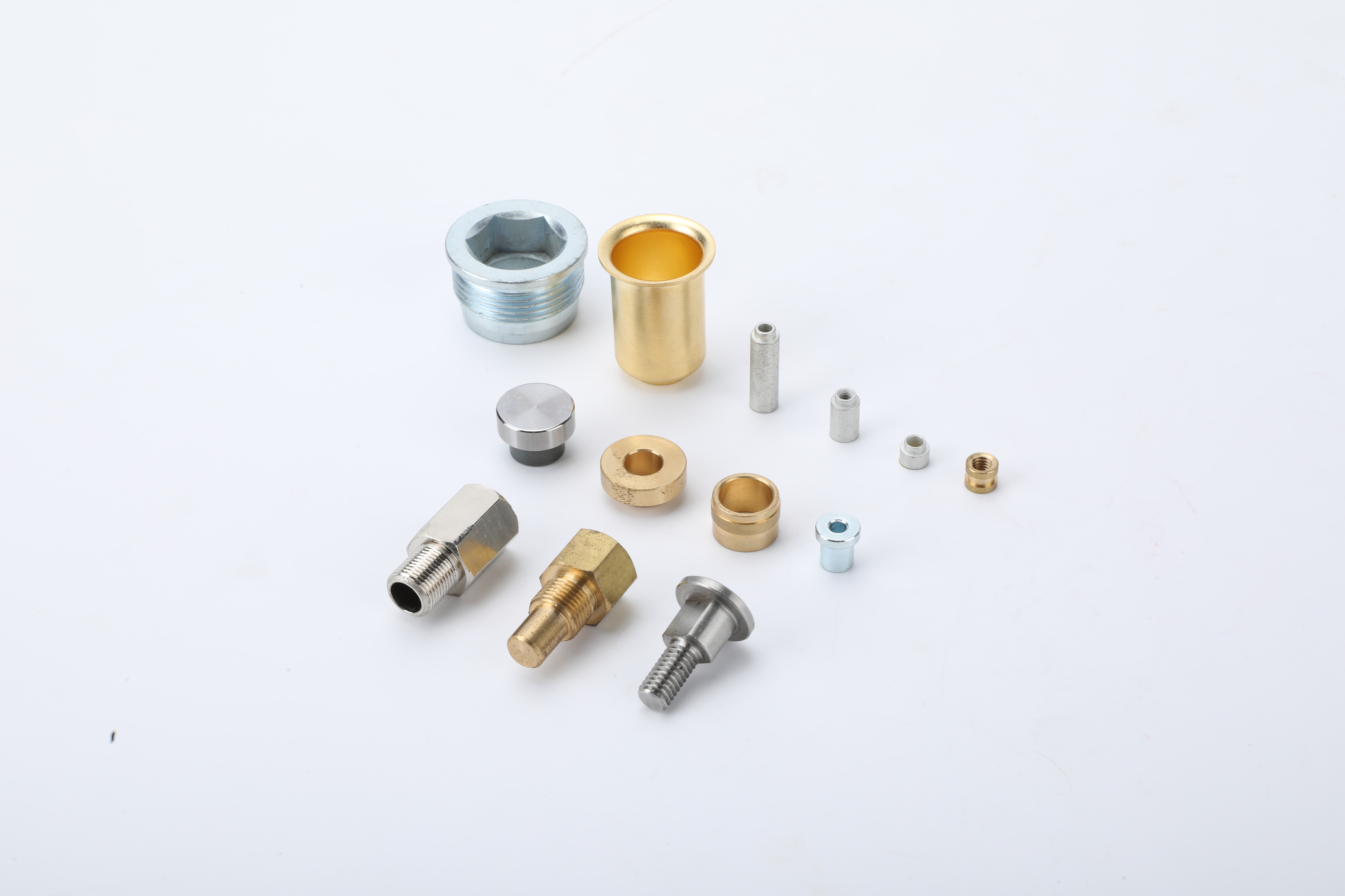
Drawing-dependent material options include C3604 brass, H62 brass, C54400 phosphor bronze and beryllium copper. State the exact grade and condition: a general “brass” or “copper alloy” note is not enough to approve substitution. For beryllium-copper projects, confirm the grade, condition and any heat-treatment responsibility before agreeing the manufacturing route.
The process review covers bar stock, multi-step turning, shoulders, grooves, chamfers and cut-off features, followed by deburring, polishing or ultrasonic cleaning where required. Drawing-controlled finishing, final inspection and protective packaging complete the agreed route. Part geometry, feature access, slenderness and the condition in which dimensions are accepted determine the final setup.
This product scope supports our custom CNC machining and Swiss-turning service. The design owner must approve any proposed change to material, geometry or finish.
Typical Tolerances for Drawing Review
| Feature | Typical capability reference | What must be defined |
|---|---|---|
| Selected mating diameters | ±0.01 to ±0.02 mm | Fit location, mating part, gauge method and acceptance before or after plating. |
| Overall length and shoulder positions | ±0.02 to ±0.05 mm | Functional datum, shoulder sequence and assembly stack. |
| Applicable concentricity or coaxial control | 0.01 mm where drawing and geometry review support it | The specific geometrical control, datum system and measurement method. |
| Straightness and other features | Drawing-specific review | Engagement length, clearance, handling risk and inspection setup. |
These references depend on part size, material condition, geometry, plating state and the production-control plan. A tighter tolerance may change the setup, inspection method, cost and lead time. The released drawing and approved quotation define the commitment.
Nickel and Gold Plating by Functional Zone
Specify the finish separately for the mating zone, retention zone and termination end. A single color description cannot define a plating system.
- Nickel underplate: a typical reviewed range is approximately 1.27–2.54 μm where the approved finish specification calls for it.
- Hard-gold mating zone: typical reviewed options are approximately 0.25–0.76 μm, or higher where the approved requirement supports it.
- Retention or press-fit zone: define where plating is required, restricted or excluded, and whether the fit dimension is accepted in the plated state.
- Solder-tail or termination zone: select the finish for the termination process. Do not assume that more gold is always better; selective finishing or a specified gold-removal requirement may be needed.
Identify the finish specification, functional boundaries, thickness-measurement locations and acceptance evidence. Finishing responsibility and the approved route are confirmed for the project; this page does not claim that every finishing operation is performed in house.
Inspection Records and Validation Responsibility
Inspection starts with the characteristics on the released drawing. Vision measurement, air gauging or CMM may be selected where suitable for the dimensions and datum setup. A first-article report can cover the agreed characteristic list, with the acceptance state and reporting format defined before production.
Production sampling requires a complete agreed plan. An AQL value such as 0.65 or 1.0 alone does not define lot size, inspection level, switching rules or acceptance and rejection numbers. Nickel and gold thickness can be checked by XRF or cross-section when specified; coating adhesion requires a method appropriate to the coating, substrate and part geometry.
A conforming loose pin does not prove the performance of a complete connector. Contact resistance, mating force, temperature rise, corrosion resistance and mating durability depend on the contact pair, housing, environment and test method. The project must identify the validation owner, test conditions and acceptance limits. No universal electrical resistance or service-life guarantee is made here.
Use the connector-pin drawing, plating and inspection guide for the detailed document and responsibility handoff.
Packaging, Quantities and Lead Times
Protective bags, trays or boxes and cartons are selected to protect mating surfaces and slender features. Carrier-tape packaging can be reviewed when orientation and automated handling requirements are defined. Packaging and lot identification are part of the quotation.
| Planning item | Typical project reference |
|---|---|
| Existing-process order quantity | Approximately 1,000–3,000 pieces, subject to setup, material, finishing and packaging economics. |
| Fully custom configuration | Approximately 3,000–10,000 pieces, subject to the project quotation. |
| Samples | Small lots such as 50–100 pieces can be reviewed. Typical sample lead time is 7–15 days after technical requirements are released. |
| Production | Typically 2–4 weeks, depending on quantity, material availability, finishing, inspection records and packaging. |
| Price basis | Setup or NRE plus piece price; no fixed catalog price is stated. |
These are planning ranges, not a binding offer or shipping guarantee. The final quotation confirms quantity, price, delivery terms, destination and schedule. A turned part does not automatically require a new mold.
Request a Connector-Pin Quotation
Send the following information so that the quotation covers the same part you intend to purchase:
- Released 2D drawing and available 3D model, with revision and document precedence.
- Material grade and condition; mating, retention and termination interfaces.
- Critical dimensions and datums, including acceptance before or after plating.
- Finish specification, functional zones and required inspection or validation records.
- Sample and order quantities, packaging needs and requested delivery destination and date.
Contact Zhengna Technology to review your connector-pin drawing.