
 EN

Two-Hole Wiring Terminals: Separate the Conductor and Mounting Requirements
A two-hole tongue can match the mounting pattern while the barrel still fails to match the intended conductor. A useful RFQ defines both interfaces and says whether the supplier is quoting a loose terminal or a completed wire connection. A photograph cannot settle either question.
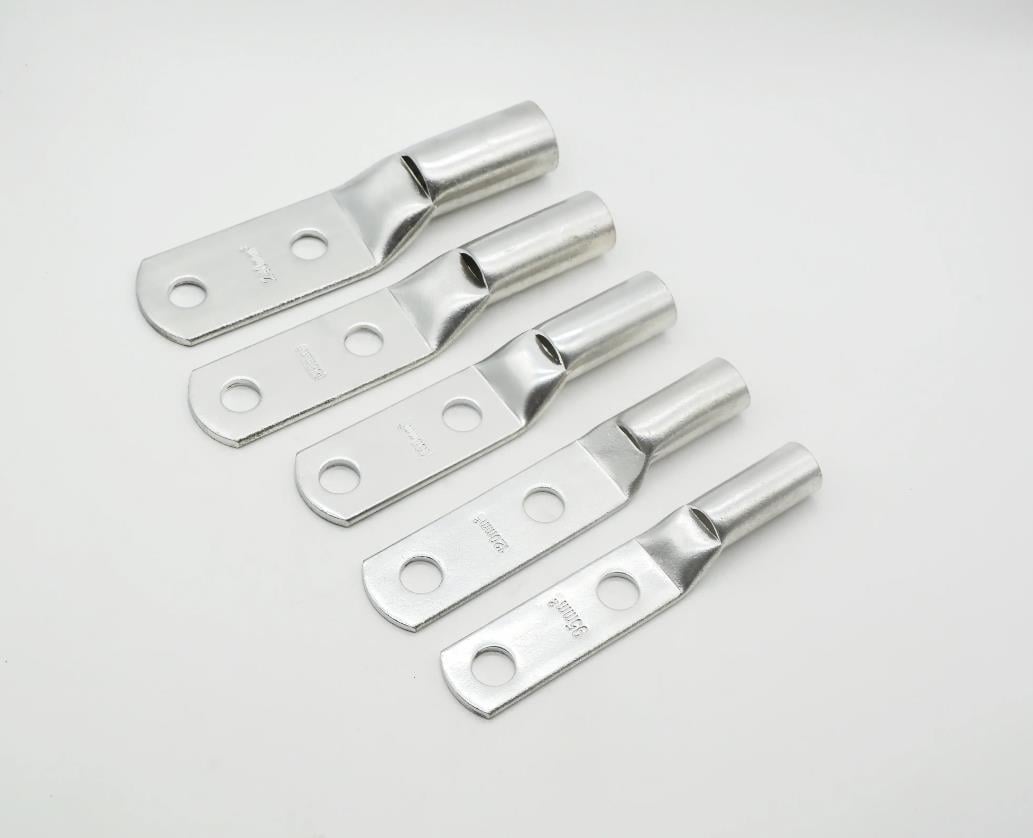
The electrical-terminal product family includes the broader contact-sourcing context. The approved photograph below shows five tin-plated brass forms with cylindrical barrels and flattened tongues with two round holes. That visible geometry is the starting point for this drawing review, not a wire-size chart or an electrical approval.
Start at the mounting surface
Show the two hole diameters, their centre distance and their location relative to the barrel. Identify the surface that must seat against the mating part. Include tongue thickness, any bend or offset, fastener access and the space available around the barrel and entering conductor. A matching bolt pattern alone does not establish contact pressure, tightening torque or current capacity.
If the tongue has a controlled flatness, contact finish or edge condition, put that requirement on the drawing with its acceptance method. Name the mating hardware or assembly specification where it controls installation. Do not choose a torque or washer arrangement from an undimensioned product image.
Then define the conductor-side connection
Provide the conductor material, cross-sectional area or AWG, strand construction, insulation dimensions and intended termination method. Define barrel internal diameter and usable length from the approved design. Outside diameter alone is not a conductor-range specification, and a visible product marking is not a released purchase requirement.
If crimp termination is specified, identify the qualified terminal, wire and tooling combination and the governing application instructions. Acceptance may require dimensional checks, a defined pull test, section review or other project-specific evidence. The required methods and limits must be agreed; they are not test results for the pictured parts. Soldering or another connection method needs its own approved process definition rather than an assumed interchangeable acceptance plan.
Agree where the supplier's responsibility ends
| Quoted supply state | Information to agree | What it does not establish |
|---|---|---|
| Loose terminal | Controlled geometry, brass grade and condition, tin specification, relevant dimensions, surface and packaging evidence | A validated wire connection or finished-system electrical rating |
| Terminated conductor, only if included in the order | Wire definition, termination process, tooling, acceptance limits, sampling, records and responsible party | Approval for an unspecified conductor, load or installation |
| Installed joint | Mating surface, hardware, tightening procedure and assembly validation responsibility | Proof obtained from a loose-part dimensional report |
For finish review, specify the tin system, controlled areas, thickness and required evidence. Do not borrow the plating thickness or inspection frequency from a different battery contact or PCB terminal order. Keep material/finish evidence, loose-part acceptance and assembled-connection validation separate.
Use application-specific acceptance, not generic crimp numbers
TE Connectivity's crimp quality guidance treats terminal, wire and tooling selection as a combination and gives precedence to the applicable product specification. Its illustrated geometries and numerical examples belong to its named products; they are not acceptance limits or approvals for Zhengna Technology's terminal family.
Before quotation, resolve three questions: which document controls each interface, what condition the supplier will deliver, and which party will validate the completed connection. Send the part revision, mating drawing, conductor details, material/finish requirements, quantities and required records through Contact Zhengna Technology. The form accepts text; agree the drawing-review method separately. The custom stamping parts page provides broader sourcing context, not confirmation of the manufacturing route for every terminal.