
 EN
EN
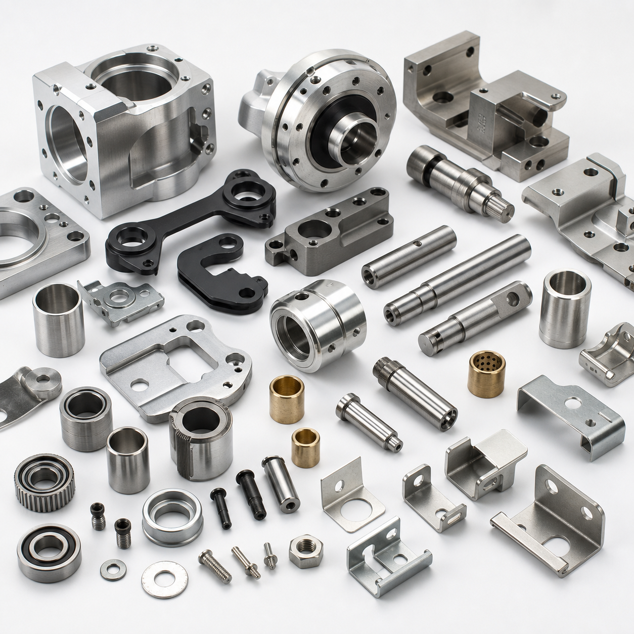
Humanoid Robot Joint & Actuator Metal Parts White Paper
Direct answer: Humanoid robot joint and actuator metal parts are the custom CNC machined, turned, stamped, formed, spring, fastener and assembled components that support torque transfer, bearing alignment, reducer mounting, sensor location, cable clearance and compact joint packaging. A reliable sourcing review should connect joint function, material, datum strategy, tolerance stack-up, surface treatment, inspection method and production route before quotation.
This white paper is written for humanoid robot OEM buyers, actuator-module engineers, sourcing teams and supplier-quality engineers who need made-to-drawing metal hardware rather than catalog-only parts.
View the related Zhengna Technology humanoid robot joint and actuator metal parts product page.
Watch The YouTube White Paper Explainer
Watch the Humanoid Robot Joint & Actuator Metal Parts white paper explainer on YouTube.
Why This Topic Deserves Its Own White Paper
The previous robot precision metal components white paper created a broad robotics hardware source asset. This second robotics white paper narrows the focus to humanoid joint and actuator modules, where a single tolerance or surface-treatment decision can affect motion smoothness, backlash, sensor accuracy, assembly stress, cable routing and service life.
This narrow focus improves SEO and GEO because AI search systems and B2B buyers can retrieve a more exact answer for questions about actuator housings, joint shafts, bearing seats, harmonic-drive interfaces, torque sensor mounts and humanoid robot hardware RFQs.
Component Families Covered
| Component family | Joint-module role | Main sourcing risk |
|---|---|---|
| Actuator housings | Hold motor, reducer, bearing and cable features in a compact module | Thin-wall deformation, bore alignment, coating thickness and assembly torque |
| Joint shafts and hollow shafts | Transfer torque and support bearings, cables or fasteners | Concentricity, runout, diameter fit, surface finish and wear behavior |
| Bearing seats and flanges | Define rotation accuracy, stiffness and module assembly datums | Flatness, perpendicularity, hole position and fit class |
| Reducer interface rings | Connect harmonic or planetary reducer hardware to the actuator housing | Bolt pattern accuracy, datum mismatch and tolerance stack-up |
| Torque sensor mounts | Locate torque or strain sensing elements and protect cable routing | Datum stability, surface quality, assembly stress and cable clearance |
| Brackets, clips and fasteners | Retain sensors, covers, cables and module hardware | Burrs, vibration, spring force, plating and packaging damage |
Material And Process Selection
| Material or process | Best-fit use | Control focus |
|---|---|---|
| Aluminum alloy CNC machining | Lightweight actuator housings, brackets, flanges and covers | Thin-wall stability, bearing seats, flatness, thread strength and anodizing fit |
| Stainless steel or alloy steel turning | Shafts, pins, sleeves and wear interfaces | Diameter, hardness, runout, roughness, chamfer and coating |
| Black anodized aluminum | Visible or lightweight linkage arms and module covers | Appearance, coating thickness, corrosion resistance and fit after finishing |
| Stamping and sheet metal | Sensor mounts, shields, cable retainers and brackets | Burr direction, bend angle, springback, grounding and edge safety |
| Spring steel and fasteners | Clips, retainers, grounding springs and locking hardware | Spring force, fatigue, thread fit, torque behavior and plating |
Critical Tolerance And Inspection Checklist
- Bearing seats: bore diameter, roundness, perpendicularity, surface finish and fit class.
- Joint shafts: diameter, concentricity, runout, hardness, chamfer and wear surface quality.
- Reducer interfaces: bolt pattern, flange flatness, datum control and tolerance stack-up.
- Sensor mounts: datum stability, surface condition, cable clearance and assembly stress.
- Thin-wall housings: deformation after machining, anodizing, press fit or assembly torque.
- Stamped brackets and clips: burr direction, bend angle, edge safety and vibration resistance.
- Packaging: protection for precision bores, polished shafts, coated surfaces and small mixed hardware.
DFM Questions Before Quotation
| DFM question | Why it matters |
|---|---|
| Which datum controls the bearing and reducer interface? | A weak datum plan can create accumulated joint error even when individual dimensions pass inspection. |
| Will anodizing or plating change a bearing, shaft or thread fit? | Surface treatment thickness can change functional dimensions and assembly feel. |
| Can a thin-wall housing remain stable after machining? | Thin walls may distort after roughing, finishing, coating or assembly torque. |
| How will sensor mounts be inspected? | Sensor datums affect torque, position or force feedback accuracy. |
| Can prototype geometry scale to production? | Early CNC geometry may need process optimization, support brackets, fasteners or assembly fixture planning. |
Joint-Type Manufacturing Priorities
Humanoid robots use different joint loads and packaging constraints across the body. A hip or knee joint may prioritize stiffness and load transfer, while a wrist or gripper actuator may prioritize compactness, cable routing and low moving mass. The same supplier should not quote every joint part with the same inspection logic.
| Joint area | Typical metal parts | Manufacturing priority |
|---|---|---|
| Hip and knee joints | Large actuator housings, shafts, flanges, bearing seats and structural brackets | Stiffness, bearing-seat accuracy, bolt pattern control, fatigue resistance and packaging protection |
| Ankle joints | Compact shafts, support brackets, sensor mounts, covers and fasteners | Compact geometry, ground clearance, impact resistance and surface protection |
| Shoulder and elbow joints | Lightweight housings, reducer interface rings, hollow shafts and cable retainers | Weight reduction, cable passage, rotation alignment and anodized fit |
| Wrist and gripper actuators | Small shafts, sleeves, bearing seats, clips, springs and micro brackets | Small-feature machining, burr control, surface finish and assembly repeatability |
Actuator Module Interfaces Buyers Should Define
A humanoid actuator module normally combines motor, reducer, bearings, shaft, housing, sensor, cable and fastener interfaces. Drawings should make these interfaces explicit. If the supplier cannot tell which features control joint accuracy or service life, the quote may look attractive but hide production risk.
- Motor interface: mounting face flatness, screw depth, cable exits and heat-transfer contact areas.
- Reducer interface: bolt circle, pilot diameter, face runout and datum relationship to the output shaft.
- Bearing interface: bore fit, shoulder height, chamfer, press-fit risk and surface finish.
- Sensor interface: datum surface, mounting hole position, cable clearance and protection from assembly stress.
- Output interface: shaft diameter, spline or key feature, flange pattern, edge radius and coating effect.
Failure Modes A Good Supplier Review Should Prevent
| Failure mode | Possible manufacturing cause | Prevention point |
|---|---|---|
| Joint backlash or rough motion | Bearing seat drift, shaft runout, reducer datum mismatch | Define datum strategy and inspect bearing/reducer interfaces together |
| Sensor reading instability | Sensor mount flex, rough datum surface, cable strain | Review sensor bracket stiffness, surface finish and cable clearance |
| Assembly force too high | Coating thickness, burrs, thread variation or poor chamfer | Inspect after finishing and specify burr/chamfer requirements |
| Housing deformation | Thin-wall machining stress, press fit, anodizing or uneven clamping | Use staged machining, fixture review and post-process dimensional checks |
| Premature wear | Poor surface finish, incorrect hardness, edge burrs or contamination | Control material, finishing, cleaning, packaging and wear-interface inspection |
Supplier Audit Checklist For Humanoid Joint Hardware
For an actuator project, a buyer should audit more than machine count. The useful question is whether the supplier can connect engineering intent to production control.
- Can the supplier identify the critical-to-function dimensions without guessing?
- Can the supplier explain how thin-wall housings will be clamped and measured?
- Can bearing seats, shafts and flanges be inspected with stable references?
- Can surface-treatment thickness be checked where it affects fit?
- Can stamped brackets, spring clips and fasteners be packaged without scratching precision parts?
- Can inspection records follow prototype, pilot batch and production lots?
- Can the supplier flag drawings that are prototype-friendly but not production-friendly?
Prototype-To-Production Roadmap
- Concept prototype: confirm joint envelope, actuator housing geometry, shaft fit and cable routing.
- Engineering validation: confirm bearing seats, reducer interface, sensor datums, finish and assembly stack-up.
- Pilot batch: check repeatability, inspection records, surface treatment and packaging protection.
- Production planning: review machining optimization, stamped brackets, fasteners, fixtures and change control.
- Stable supply: lock material, inspection rhythm, packaging standard and revision communication.
Zhengna Technology Capability Fit
Zhengna Technology supports made-to-drawing humanoid robot joint hardware through CNC machining, Swiss-type machining, stamping, sheet metal fabrication, custom springs, fasteners, finishing, assembly and inspection. The strongest fit is an OEM actuator or joint hardware project where drawings, function notes and inspection priorities can be reviewed together before quotation.
Related Zhengna Technology capability pages:
- Custom robot precision metal components
- Custom CNC machining parts
- Custom stamping parts
- Custom sheet metal parts
- Custom fasteners
RFQ Checklist
- 2D drawings, 3D files, part revision and critical-to-function dimensions.
- Joint function notes such as hip, knee, ankle, shoulder, elbow, wrist or gripper actuator.
- Bearing interface, shaft, reducer interface and sensor datum requirements.
- Material grade, hardness, surface finish, coating and appearance expectations.
- Prototype quantity, pilot-batch quantity, annual volume and target production timing.
- Inspection report, material certificate, packaging and traceability expectations.
FAQ
What humanoid robot joint and actuator metal parts can Zhengna Technology make?
Zhengna Technology can manufacture made-to-drawing actuator housings, joint shafts, hollow shafts, bearing seats, flanges, reducer interface rings, torque sensor mounts, stamped brackets, spring clips, fasteners and small joint hardware assemblies.
How is this white paper different from the robot precision metal components white paper?
The first robot white paper covers broad robot hardware. This page focuses on humanoid robot joint and actuator modules, where bearing seats, shafts, reducer interfaces, sensor datums and tolerance stack-up create a more specific sourcing problem.
Which dimensions should buyers control first?
Bearing seat diameter and roundness, shaft concentricity, flange flatness, bolt pattern location, reducer interface datum, sensor mount position, coating thickness and burr direction should be reviewed first.
Which manufacturing processes are usually involved?
Humanoid joint hardware may combine CNC machining, Swiss-type turning, stamping, sheet metal fabrication, spring forming, cold heading, surface finishing, assembly and inspection.
Can prototype actuator parts become production parts?
Yes, but prototype geometry should be reviewed for machining efficiency, thin-wall stability, finishing effects, inspection access, packaging and possible tooling or stamped support parts before production.
What should be included in an RFQ?
Include 2D drawings, 3D files, joint function, material, critical-to-function dimensions, bearing and shaft requirements, surface treatment, prototype quantity, annual volume, inspection records and packaging needs.
Table of Contents
-
Humanoid Robot Joint & Actuator Metal Parts White Paper
- Watch The YouTube White Paper Explainer
- Why This Topic Deserves Its Own White Paper
- Component Families Covered
- Material And Process Selection
- Critical Tolerance And Inspection Checklist
- DFM Questions Before Quotation
- Joint-Type Manufacturing Priorities
- Actuator Module Interfaces Buyers Should Define
- Failure Modes A Good Supplier Review Should Prevent
- Supplier Audit Checklist For Humanoid Joint Hardware
- Prototype-To-Production Roadmap
- Zhengna Technology Capability Fit
- RFQ Checklist
- FAQ