
 EN
EN

CR2032 Coin Cell Holder PCB Selection and RFQ Guide
Select a CR2032 holder by documenting the board, enclosure, cell-access, retention, terminal, assembly, and validation requirements before comparing suppliers. A holder that accepts the cell can still fail the product if the footprint is wrong, the battery cannot be removed, the polarity is ambiguous, the terminal process is uncontrolled, or the enclosure interferes with insertion.
Freeze the cell and holder definitions separately
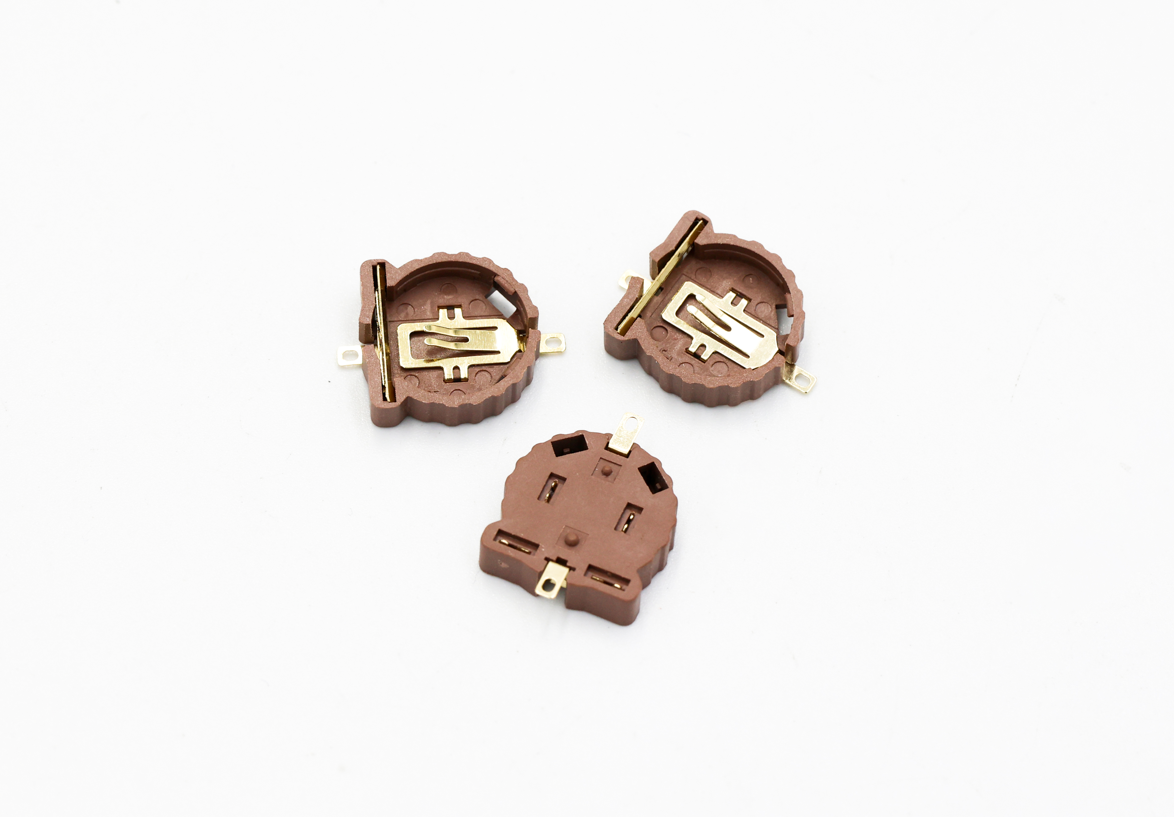
CR2032 is the confirmed compatible cell family for the pictured holders, but the buyer should still identify the controlled cell drawing or specification and any approved supplier range. Separately control the holder drawing and revision. Do not assume that all products sold under the same common cell name have identical dimensional limits or terminal surfaces.
The holder drawing should define the base envelope, cell seating references, retaining geometry, terminal positions, board references, critical clearances, allowed edge condition, and delivered state. The board drawing should define the corresponding holes, pads or interface features, keep-out, polarity documentation, assembly side, and inspection datums.
Use a board and enclosure decision table
| Decision | Questions before layout release | Evidence to retain |
|---|---|---|
| Footprint and datums | Which holder surfaces and terminal features locate the part? Which drawing controls the PCB relationship? | Released holder and PCB drawings, approved model, and dimensional sample report. |
| Polarity documentation | How are cell orientation, terminal identity, board markings, assembly instruction, and inspection aligned? | Controlled schematic/layout references and an approved inspection method. |
| Insertion and removal | Which angle, direction, finger or tool access, force limit, and enclosure opening apply? | Assembly trial, service review, and project-defined acceptance evidence. |
| Retention | Which movement, shock, vibration, handling, and replacement conditions must the design withstand? | Responsible validation plan with named cell, sample count, method, and limit. |
| Terminal process | Is the terminal soldered or assembled by another controlled method? Which material, finish, heat, cleaning, and board limits apply? | Approved process and validation records; never infer reflow suitability from appearance. |
| Keep-out and shorting risk | Which conductive surfaces, components, tools, covers, debris, and user actions can contact the cell or terminals? | Layout and enclosure review with documented clearances and protective measures. |
Separate retention, contact, and service functions
A metal feature can contribute to retention, electrical contact, or both, but the drawing and validation should identify each function explicitly. Excessive retention can damage the cell, holder, solder joint, or board during service. Insufficient retention can permit intermittent contact or ejection. The correct balance depends on the exact geometry, materials, finish, cell, assembly, environment, and replacement expectation.
For replaceable cells, examine how the user reaches the cell without slipping a conductive tool across terminals or adjacent components. For factory-installed cells, define handling, polarity verification, traceability, and the response to a damaged or incorrectly seated cell.
Plan validation by responsibility
| Validation layer | Typical question | Responsible evidence |
|---|---|---|
| Holder component | Does the supplied holder match the controlled drawing and agreed material/finish records? | Supplier dimensional, visual, material, finish, assembly, and lot evidence as contracted. |
| PCB assembly | Are terminal location, joint or attachment, polarity, cleanliness, and board interaction acceptable? | Assembly-process and board-level inspection or test owned by the agreed party. |
| Finished device | Does the product meet electrical, safety, access, shock, vibration, environmental, and life requirements? | Design-authority validation using the released device and controlled cells. |
Do not allow a component dimensional report to stand in for finished-device approval. Conversely, a device-level failure should be traced to the holder, board, cell, assembly, enclosure, use condition, or interaction before changing the component drawing.
Supplier RFQ checklist
- holder drawing, PCB drawing, enclosure model, revision, units, and governing-file order;
- controlled CR2032 cell definition, approved range, insertion orientation, and polarity documents;
- terminal and board interface, keep-out, assembly method, cleaning, and inspection datums;
- retention, insertion, removal, service access, shock, vibration, environment, and validation ownership;
- delivered holder scope, manufacturing and assembly responsibility, material and finish records;
- prototype, sample, pilot, production, and forecast quantities;
- packaging, orientation, labels, traceability, change notification, and nonconformance process.
Review the paired custom CR2032 coin cell holder commercial page, the precision PCB hardware parent, quality-control evidence, or send the holder, PCB, and enclosure package for RFQ review.
Questions buyers ask
Should the PCB footprint be copied from a photograph?
No. Use the released holder drawing and terminal definition. A photograph cannot establish dimensions, datums, tolerances, pad or hole geometry, polarity, solder process, or keep-out.
What should be checked around the battery access path?
Check insertion angle, removal tool or finger access, enclosure opening, neighboring components, conductive surfaces, accidental shorting, cell ejection, and service instructions.
Does CR2032 compatibility prove electrical suitability?
No. Compatibility identifies the pictured holder forms for CR2032 cells. Electrical rating, resistance, temperature rise, life, shock, vibration, safety, and finished-device behavior require project-specific evidence.
What belongs in a supplier comparison?
Compare delivered scope, drawing control, approved materials and finishes, terminal and base inspection, sample validation, packaging, traceability, change control, and the evidence included with quotation and production release.
Authorship and evidence boundary
Published by Zhengna Technology on 2026-07-20. The guide uses a user-approved photograph of a holder confirmed compatible with CR2032. It is a drawing and supplier-decision framework, not a datasheet, footprint, electrical rating, reflow approval, safety certification, or finished-device validation.