
Zhengna Technology | Drawing and acceptance guidance | 27 October 2026
A thin-wall housing can be measured on a bench, held in an inspection fixture or fastened to its mating assembly. Those are different conditions. Before a supplier and buyer compare results, the drawing and inspection agreement should identify which condition applies to each critical feature.
Do not tighten a housing into an apparently acceptable shape and report that result as an unrestricted part measurement. Equally, a free-state reading alone does not answer whether the specified installed interfaces will align. If both conditions matter, give them separate acceptance requirements and separate records.
Free-state inspection addresses the part without an imposed assembly load. A restrained check uses a defined setup to represent the specified support or installed condition. The KEYENCE guide to non-rigid-part GD&T explains why free-state conditions, orientation and restrained checks need explicit indications. The applicable drawing standard and revision govern the actual requirement.
Not every thin-wall housing should be classified as non-rigid. A photograph cannot establish its stiffness, free-state deviation or compliance with a tolerance. The practical first step is to ask which feature is function-critical, how the part is supported and whether assembly loads may change the feature being measured.
| Interface or feature | Decision to put in the review | Record to retain |
|---|---|---|
| Mounting-ear seating faces | Is the requirement for the unfastened part or for contact with a specified mating base? | Datum references, support locations and the stated inspection condition. |
| Hole or connector-opening location | Which datum scheme locates the opening, and does the requirement apply to the finished part? | Drawing revision, measured feature and coating stage. |
| Cover or inserted-component clearance | Is acceptance dimensional, a defined assembly check, or both? What mating geometry is controlled? | Separate dimensional result and assembly-check result where required. |
| Wall form or local flatness | May the setup restrain the surface? If so, where and under what agreed conditions? | Fixture/setup identification, orientation and specified restraint; not only a pass/fail label. |
For an agreed restrained check, identify the locating features, support points, fastener or clamp locations and any required tightening sequence or load. These values must come from the approved drawing or inspection agreement, not from a generic machining article. Do not invent a universal clamp force or torque.
A setup photograph can explain where the part rests, but it does not replace the setup specification. Keep the measurement report tied to the drawing revision and fixture identity. If two parties obtain different results, compare their support, alignment, finish stage and restraint before changing a tolerance or declaring the part nonconforming.
Specify whether critical dimensions apply before or after finishing, and identify any masking or contact-area requirement. A dimensional check is not evidence of enclosure sealing, electrical insulation, grounding performance or electromagnetic shielding. If the application needs one of those functions, define its acceptance method and required evidence separately.
The same boundary applies to a trial assembly. A cover that can be fitted is useful assembly information, but it does not by itself prove every drawing dimension or a named environmental rating.
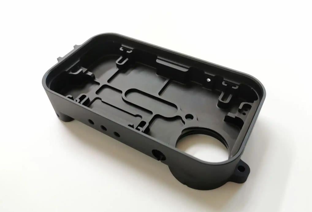
This is an approved real Zhengna Technology thin-wall CNC aluminum-alloy electrical-housing photograph. An electrophoretic finish is confirmed. No wall measurement, restraint setup, tolerance result or IP/EMI test is evidenced by this image.
See the aluminum CNC milling product page and housing example for the commercial scope and interface inputs. The custom CNC machining parts page covers the broader manufacturing route.
For a quotation or acceptance-method review, contact Zhengna Technology with the drawing revision, mating geometry, material and finish requirements, critical features and proposed free-state or installed inspection conditions. Leave unresolved limits explicitly open for engineering agreement; do not convert a generic checklist into a claimed test result.

 EN