
 EN
EN

Polypropylene Injection Molding: Shrinkage, Warpage and RFQ Guide
Polypropylene injection molding should be specified as a material, geometry, tooling, process and measurement system—not as a single shrinkage percentage. An RFQ becomes useful when it identifies the exact PP grade or approval route, functional datums, flow-sensitive features, allowed appearance, conditioning state, measurement method, sampling plan and assembly validation owner.
This guide helps OEM engineers, sourcing teams and supplier-quality reviewers prepare that package. It does not prescribe a universal process window. Final feasibility and acceptance depend on the released drawing, resin supplier data, mold design, trial evidence and the buyer's functional requirements.
Begin with the exact resin definition
“PP” is not a complete material specification. A buyer may be considering a homopolymer, copolymer, filled formulation, impact-modified grade, recycled-content requirement or another project-specific material route. Those choices can change flow, shrinkage, stiffness, impact response, surface appearance, dimensional movement and processing conditions. Color concentrate, additive package, approved supplier, substitution rules and required declarations can matter as much as the base polymer name.
The RFQ should state either the exact approved grade or the performance and compliance route by which an alternative can be reviewed. If substitutions are permitted, record who approves them and which sampling or validation work must be repeated. Zhengna Technology reviews the supplied material requirement as part of a made-to-drawing molding project; this page does not claim that one PP grade is suitable for every application.
Shrinkage needs direction, timing and context
Mold shrinkage is not one transferable catalogue number. Part geometry, wall transitions, gate location, flow direction, packing, cooling, local constraint and material formulation can create different movement along and across the flow path. The dimension measured immediately after ejection may also differ from the dimension measured after an agreed conditioning period.
ISO 294-4:2018 describes moulding and post-moulding shrinkage for injection-moulded thermoplastic test specimens in directions parallel and normal to melt flow. That distinction is useful when framing a PP review, but a standardized test specimen is not the buyer's production part. Use resin data and trial results as inputs, then confirm the actual geometry under the agreed measurement condition.
| Question | What the RFQ should define | Evidence after tooling |
|---|---|---|
| Which material state applies? | Exact grade, color/additives, approved source, recycled-content rule and substitution control | Material identification and lot record required by the project |
| Which direction matters? | Flow-sensitive dimensions, ribs, holes, bosses and assembly interfaces | Cavity and measurement results related to the actual flow path |
| When is the part measured? | Time after molding, temperature, humidity or other conditioning agreed by the parties | Report showing the stated timing and condition |
| Is the part free or restrained? | Support points, fixture, mating part, restraint force and datum scheme | Repeatable fixture or measurement setup |
Define warpage by function, not by a vague flatness request
Warpage becomes actionable only when the drawing identifies the surfaces and interfaces that control assembly. A thin cover, long rail, snap feature, sealing-adjacent face or connector housing may need different acceptance logic. Mark functional datums and state whether the part is evaluated free-state, supported, clamped or assembled. A supplier and buyer can otherwise measure the same part in different physical states and reach conflicting conclusions.
ISO 20457:2018 provides a framework for tolerances and acceptance conditions for plastic moulded parts. It does not replace functional product requirements or settle surface imperfections such as sink, flow structures and joint lines. The buyer should therefore add the characteristics that matter to fit, function and appearance instead of relying on a general tolerance reference alone.
Use a cause-and-evidence sequence for warpage
- Confirm the drawing state. Verify revision, datums, critical interfaces, free or restrained condition, temperature and measurement timing.
- Review material and geometry together. Identify wall changes, ribs, bosses, long unsupported areas, living features, inserts and flow-sensitive dimensions.
- Review the mold concept. Connect gate, runner, venting, cooling, ejection and cavity layout to the functional features. A gate decision is also a flow-orientation, weld-line, packing and appearance decision.
- Run structured trials. Record the material lot or approved identity, tool revision, cavity, machine, stable settings, sample stage and relevant dimensions. One visually acceptable shot is not a production window.
- Measure under the agreed condition. Use the same datum, fixture, support, time and temperature rules for comparison.
- Separate correction from proof. A parameter or tool change should be followed by repeatable evidence; a temporary improvement on one sample does not establish ongoing control.
ISO 294-4 separates moulding shrinkage and post-moulding shrinkage determinations in directions parallel and normal to melt flow. That test framework helps define what to measure; it does not supply a universal shrinkage value for a specific drawing.
Gate, weld line and appearance requirements belong in the drawing package
| Buyer concern | Define before quotation | Review during sampling |
|---|---|---|
| Gate witness | Allowed location, trim condition, protrusion or recess limit and cosmetic zone | Actual gate vestige against an approved sample or drawing rule |
| Weld line | Critical load, sealing, clip, hinge or cosmetic areas where a weld line is restricted | Location, appearance and project-specific functional evidence |
| Sink and read-through | Visible surfaces, gloss/texture target, ribs and bosses behind cosmetic faces | Lighting and viewing method plus agreed reference standard |
| Flash and mismatch | Parting-line zones, assembly interfaces and handling limits | Visual and dimensional evidence at the relevant features |
| Color and contamination | Color reference, regrind rule, black-speck/foreign-material criteria and cleaning/handling expectation | Approved sample and batch inspection method |
Do not convert appearance language into an unsupported universal guarantee. Agree on samples, lighting, viewing distance, measurement tools or defect limits that suit the actual product.
Build an inspection plan around the assembly risk
A long dimensional report can still miss the features that decide whether a PP part works. Connect each critical characteristic to its method, timing, fixture, frequency and reaction rule. For a flexible or thin molded part, the fixture may have as much influence as the instrument. For a multi-cavity tool, cavity identity may be necessary to diagnose a pattern.
- Mark the drawing revision and material requirement on the inspection record.
- Define datum establishment, support points and any restraint applied during measurement.
- Record time after molding and conditioning where dimensional movement is relevant.
- Identify cavity when the tool has more than one cavity and cavity-to-cavity evidence matters.
- Separate dimensional acceptance from assembly, leak, electrical, chemical, fatigue or regulatory validation owned elsewhere.
- State the sampling and reaction plan for a failed characteristic; avoid phrases such as “full inspection” without a method and scope.
PP molded-part RFQ checklist
| RFQ field | Minimum useful input |
|---|---|
| Controlled part data | 2D drawing, 3D model, revision, units, datum scheme and governing-document precedence |
| Material | Exact PP grade or approval route, color/additives, allowed source, declarations and substitution control |
| Functional requirements | Mating parts, loads, clip/hinge behavior, sealing-adjacent surfaces, temperature and chemical exposure |
| Geometry and appearance | Wall transitions, ribs, bosses, inserts, draft, gate restrictions, texture, color and defect criteria |
| Dimensional acceptance | Critical features, free or restrained state, conditioning time, fixture, method and reporting format |
| Tooling | Ownership, cavity plan, trial stages, maintenance, spare/wear parts and change approval |
| Volume and schedule | Prototype, pilot and production quantities, annual forecast, delivery location and launch timing |
| Evidence | Sample report, material documentation, cavity identity, inspection plan, traceability and packaging approval as required |
Where Zhengna Technology fits
Zhengna Technology supports made-to-drawing plastic injection molded parts with drawing and material review, tooling coordination, sampling, molding control, dimensional inspection and shipment preparation. The useful first step is a controlled RFQ package rather than a generic request for “PP parts.”
Review the custom injection molded parts capability, the injection-molding supplier audit guide, the injection-molding cost and quality guide and the quality-control context. Then use the contact page to describe the project and arrange controlled drawing transfer through the agreed sales channel.
Project feasibility remains subject to the released geometry, material, tool concept, machine fit, validation plan and responsible approvals. This guide does not claim a fixed PP shrinkage value, universal tolerance, standard process window, guaranteed warpage result, certification, capacity, MOQ or lead time.
Frequently asked questions
What should a buyer specify for a polypropylene injection molding quote?
Send the controlled drawing and model, exact PP grade or approval route, color/additives, functional interfaces, critical dimensions, appearance zones, annual volume, tooling requirements, measurement condition, validation needs and packaging expectations.
Can one PP shrinkage percentage be used for every dimension?
No. Material formulation, flow direction, geometry, gate, packing, cooling and constraint can produce different movement. Use resin data and tool design assumptions for planning, then confirm the actual part through structured trials and agreed measurement conditions.
How should PP warpage be measured?
The drawing or inspection plan should define the functional surface, datums, support or restraint, temperature, time after molding, conditioning state, fixture, instrument and reporting method. Without those conditions, results may not be comparable.
Does ISO 20457 automatically define acceptance for a PP part?
No. It provides a framework for moulded-part tolerances and acceptance conditions. Functional product requirements, surface criteria, assembly validation and any sector-specific rules still need project-specific definition.
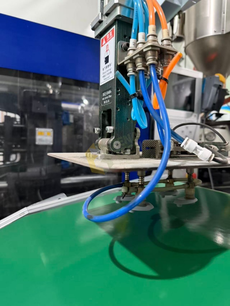
What does the workshop image prove?
It is representative evidence of a Zhengna Technology injection-molding workshop. It does not prove that a particular PP grade, tool, dimension, process window or validation result has been approved.
Sources and review boundary
- ISO 294-4:2018 — determination of moulding shrinkage
- ISO 20457:2018 — plastics moulded parts tolerances and acceptance conditions
Published and reviewed: July 25, 2026 by Zhengna Technology. Sources structure buyer questions; they do not establish a Zhengna Technology certification or project result.