EN

Anodized Aluminum Stamped Robot Bracket
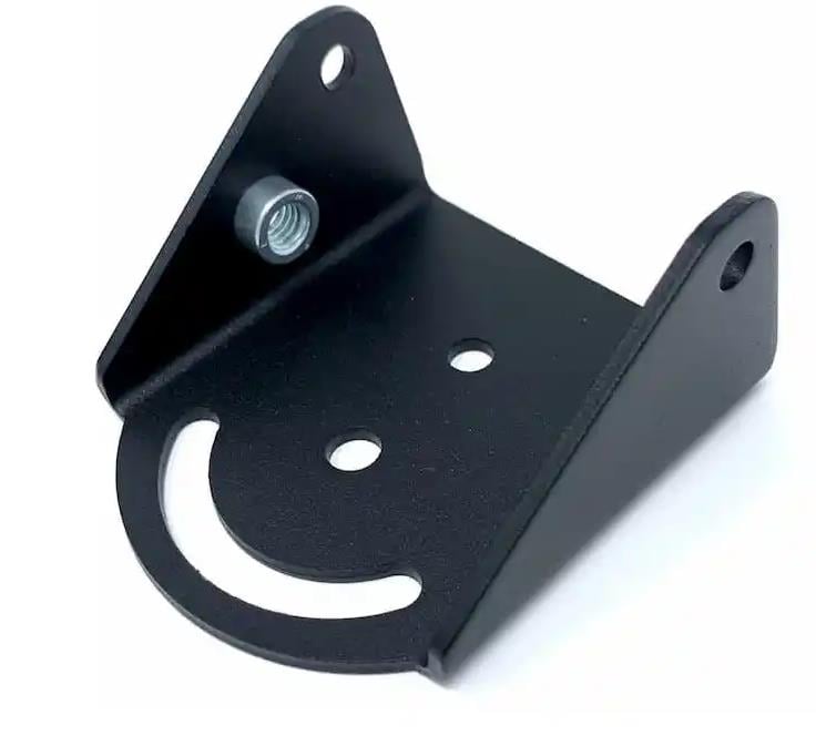
Zhengna Technology supplies the anodized aluminum-alloy stamped robot component shown below. Its U-shaped body combines two raised side walls, round holes, a curved slot and a visible threaded feature. Use this real part as a starting point for a drawing-based bracket enquiry, not as a dimensioned catalogue item or a rated robot accessory.
Compare the interfaces, not just the outline
The base has round openings and a curved slot; the side walls contain additional holes. A drawing review needs to relate these features to the surfaces that locate the bracket in the assembly. Show which hole establishes position, whether the slot permits adjustment, and which face seats against the mating component. The photograph alone does not identify those functions.
The visible threaded feature needs its own callout. State the thread standard, size, engagement and acceptance requirement. Also identify whether the required design uses a tapped feature or a separate insert and who controls its installation. Neither the insert material nor its attachment method has been confirmed for the photographed sample.
What is confirmed for this example
| Confirmed evidence | Required from the drawing or order |
|---|---|
| Aluminum-alloy stamped robot component | Alloy, temper, stock thickness and controlled part identity |
| Anodized finish; black appearance in the real photograph | Finish specification, type, colour acceptance, thickness, sealing and any masked zones |
| Formed side walls, round holes, curved slot and threaded feature are visible | Dimensions, datums, tolerances, bend geometry, thread definition and mating clearances |
The exact robot installation, compatible models, load, stiffness, electrical function and service life have not been established. The sample is not identified as a safety-critical, sensor, gripper or actuator bracket. Those uses must be reviewed against the buyer's actual design rather than inferred from its shape.
Specify the delivered condition
Separate the formed-part requirements from the finished interfaces. Mark the dimensions that apply after anodizing, the faces that contact other parts, and any areas where a coating boundary or rack-contact mark would interfere with fit or appearance. If a thread or locating hole must be protected, define the required surface condition instead of relying on a general “black anodize” note.
The anodized bracket finished-interface review explains how to define those decisions. For alloy selection, springback, galling and edge conditions before finishing, use the separate aluminum stamping DFM guide.
Start a controlled quotation review
Provide the drawing revision and model if available, material and temper, thickness, hole and slot requirements, thread details, finished-state dimensions, finish zones, quantities and required inspection records. Identify the mating part or explain the function of each critical interface. Sampling, methods and acceptance limits must be agreed for that drawing; no measured result is published for this sample.
Tooling route, secondary operations, treatment responsibility, MOQ, packaging and delivery timing remain quotation items. This product record does not establish a progressive die, an in-house anodizing line or a fixed delivery promise.
See the broader custom stamping parts service, or contact Zhengna Technology about the bracket drawing. The Contact form accepts text; describe the project and ask how to arrange the drawing review rather than expecting an attachment field.